This article outlines all of the steps I use when I shape a core on my CNC machine, starting with a Cleanup after inlay, and final blank sizing along the effective edge. The core blank has alignment holes left over from the inlay process which allows me to re-register the part properly on the CNC machine.
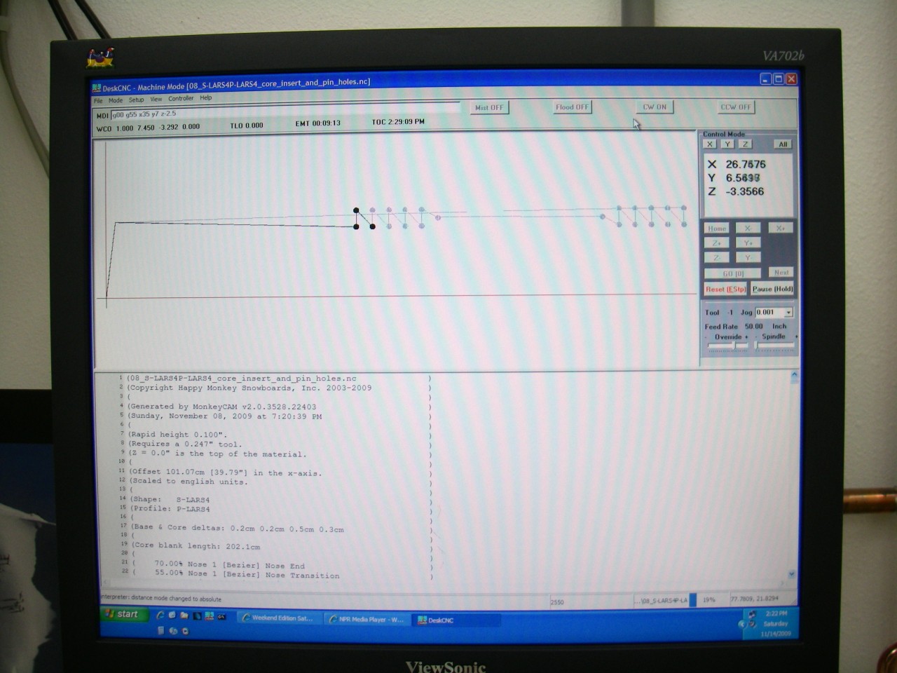
Here is a short video which shows each step of shaping a core from blank to final core, including all of the CNC programs.
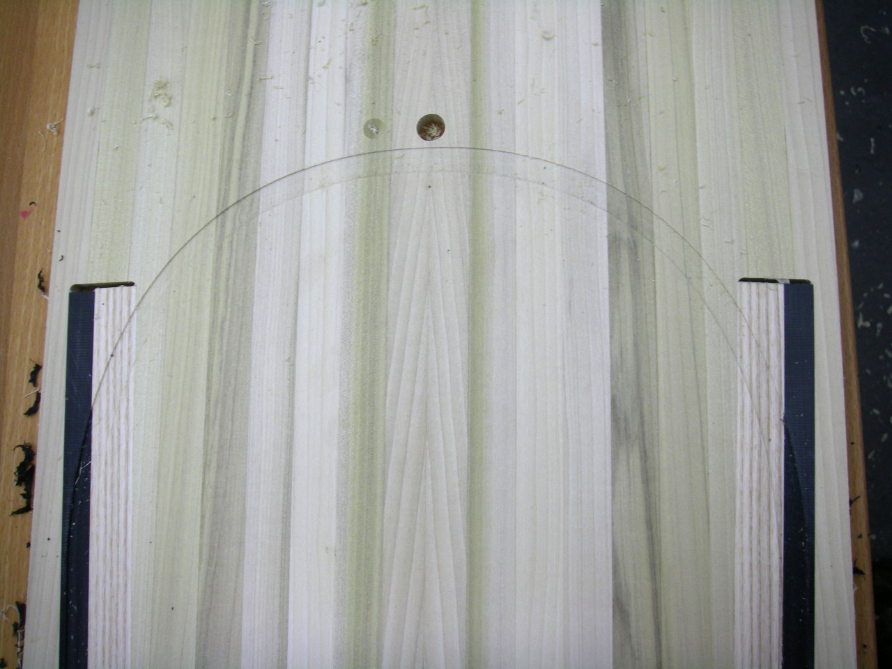
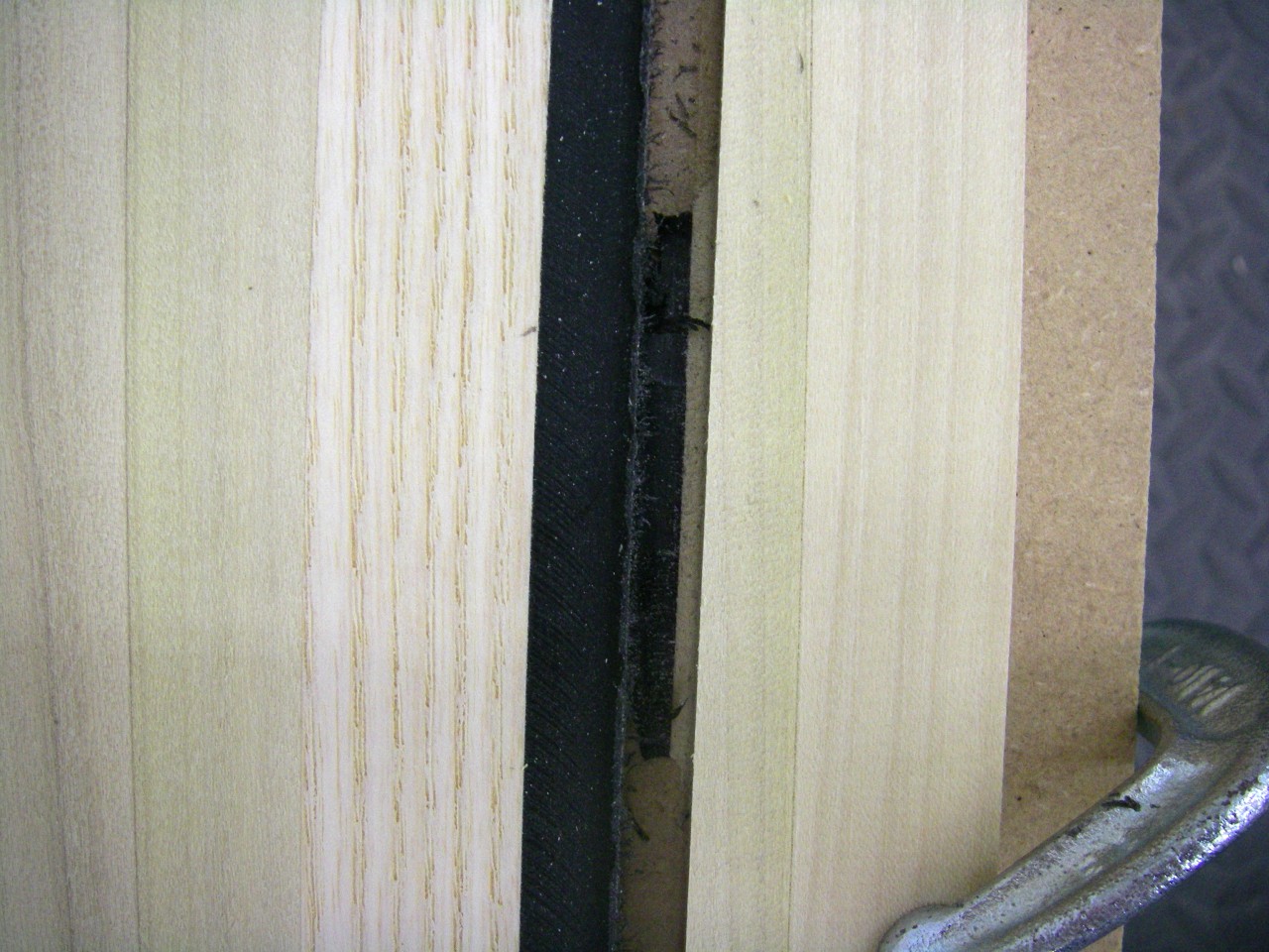
Edge relief and alignment marks #
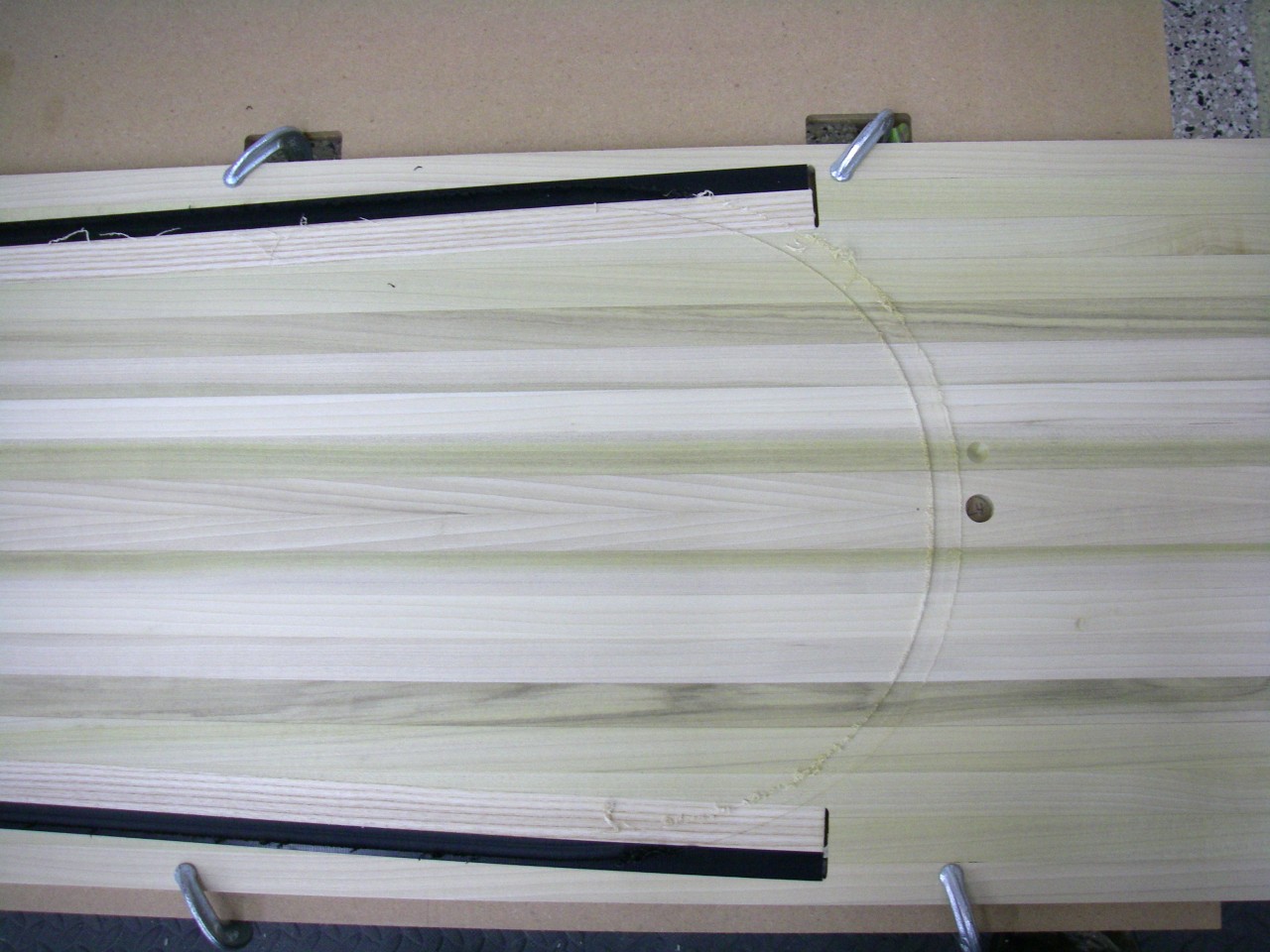
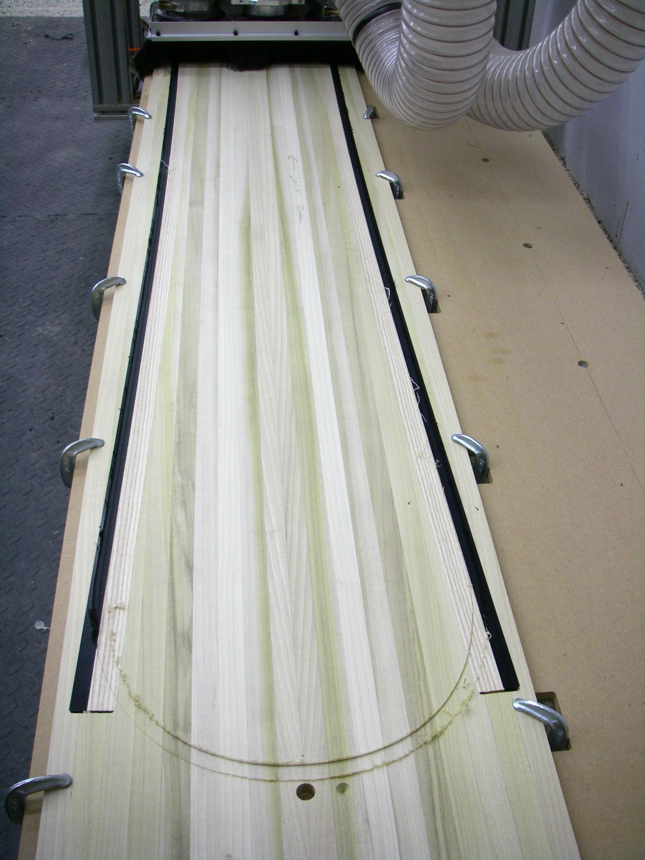
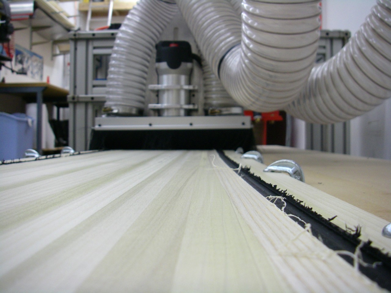
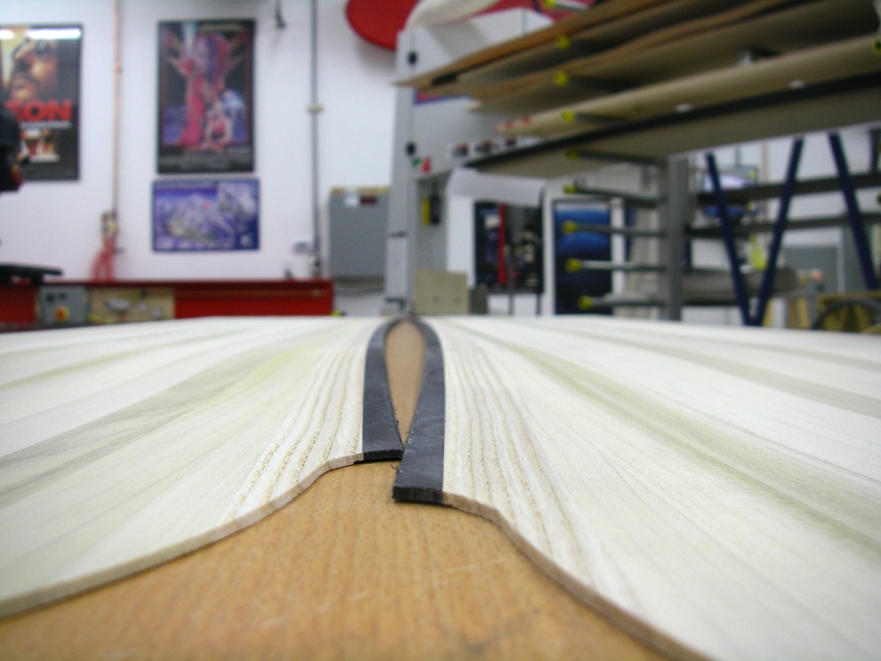
The first stage in CNC cutting the core is to create a shallow relief for the edge material along the perimeter of the core. About 0.025” of the wood and sidewall material is removed to make room for the edge and to allow the core to sit flat across the full width of the base. This step is critical to ensuring that the base comes out as flat as possible right out of the press. This also ensures there is no void between the core and the base near the edge. A void in that area would be epoxy-rich, and thus weaker. This is cut with a 1/4" upcut spiral bit.
Small alignment marks (divots) are also left by the CNC machine on what will be the final core. These indicate the actual center of the core and the center of the effective edge. These are used later after the core is registered to the base; the marks are transferred to the edged base and then used to align the base in the mold. These are cut with a 1/4" v-groove bit, sunk into the part about 0.030”.
Edge relief #
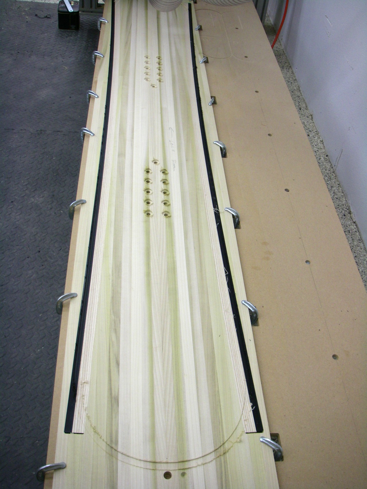
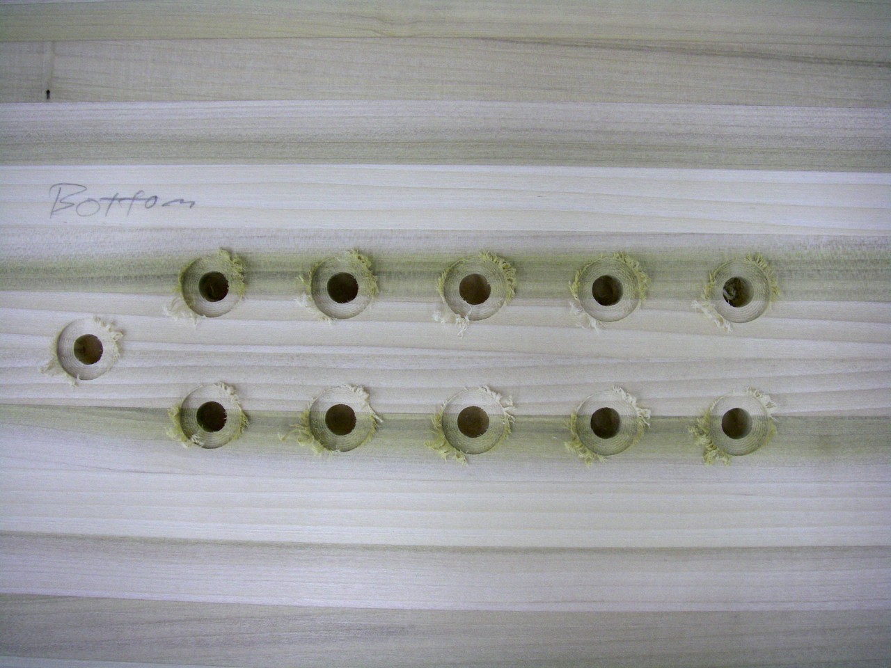
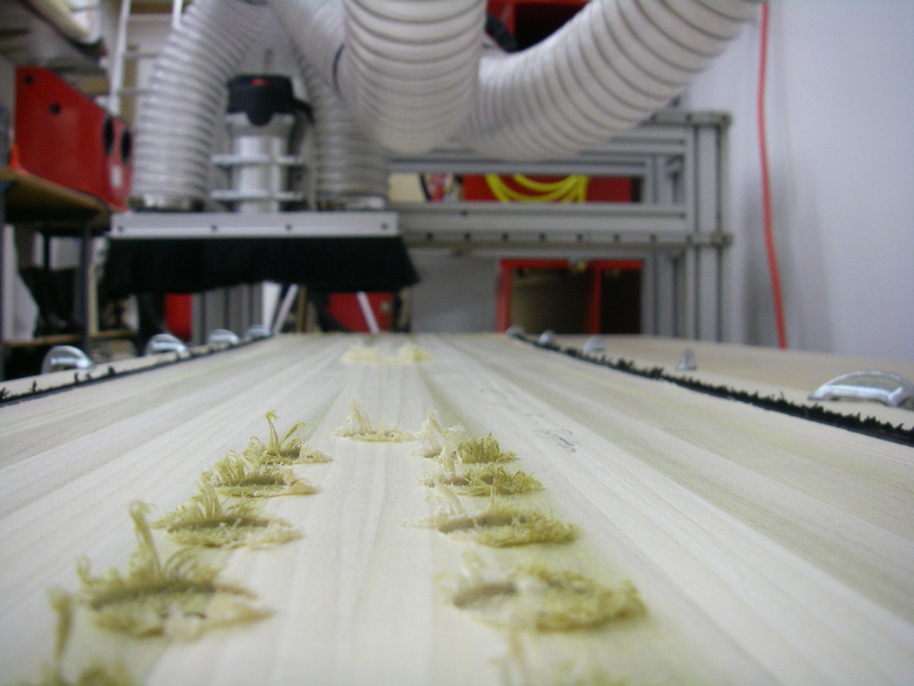
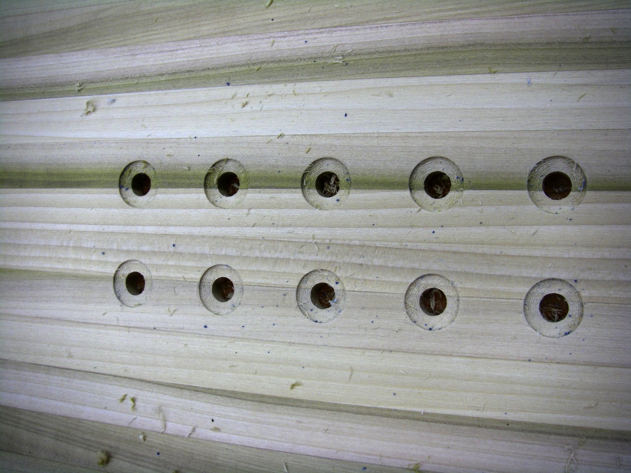
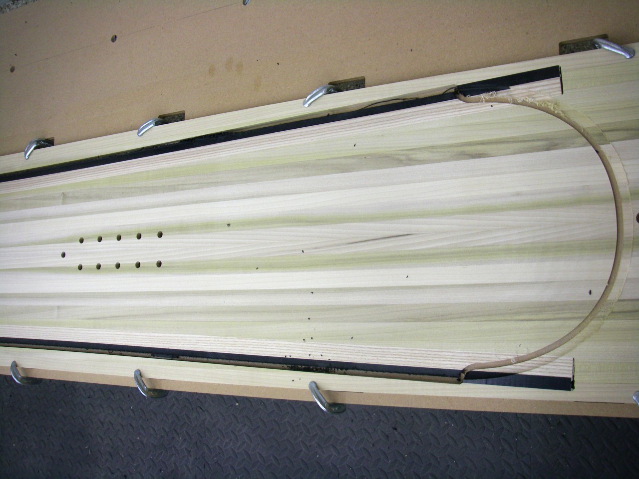
Inserts and alignment holes #
Next, I cut the insert and alignment holes. The insert holes are a snug fit for the inserts; I leave just enough room for the insert to press in along with a little epoxy and Kevlar backing. The inserts themselves are very similar to T-nuts, but the flange is rounded instead of flat. I’ve carefully matched the profile of the insert flange with the CNC to ensure that I get a perfect bond between the core and the insert flange. The larger, shallow holes are actually subtle bowls, cut in about 7 concentric circles at varying depths. This is done with a 1/4" upcut spiral bit.
As you will see later, I use two specially placed inserts along the center axis of the board to provide perfect alignment of the core and base during layup. Those are the extra insert holes you see centered at each insert pack.
Inserts #
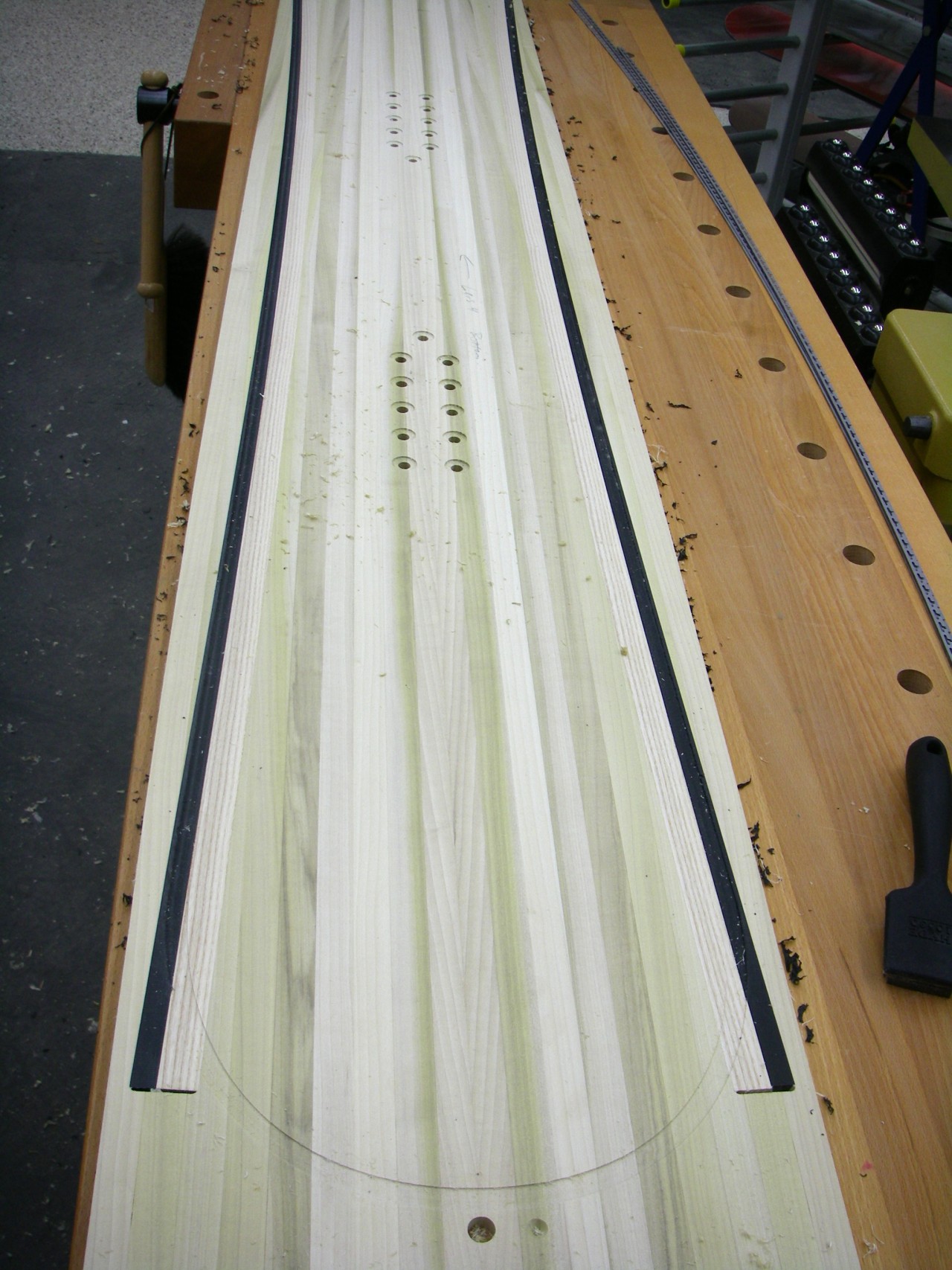
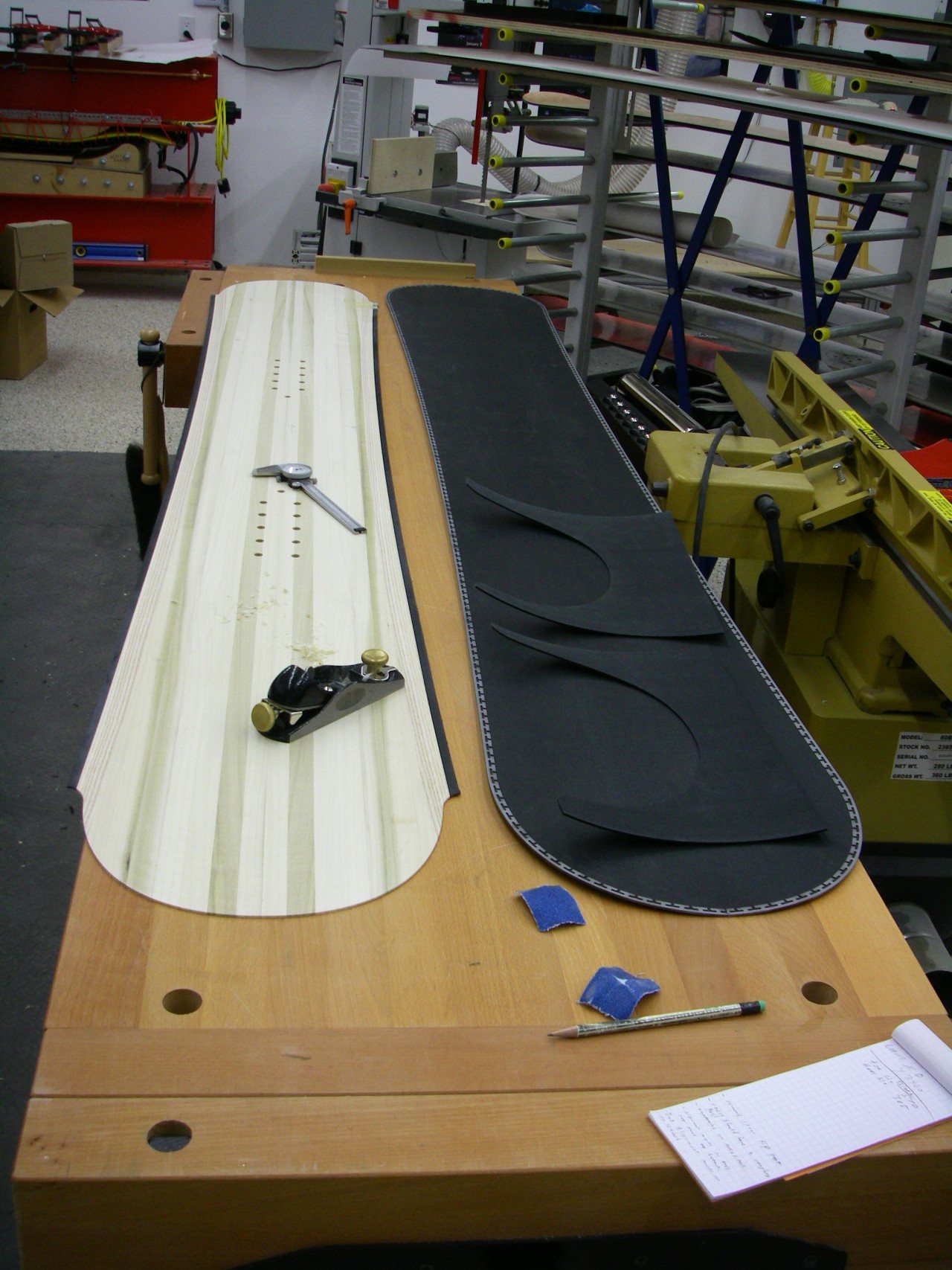
Cleanup on the bottom before flipping #
Once the bottom of the core is done (insert holes, edge relief, alignment marks), it must be flipped over so the top can be profiled. It’s imperative that the core sit perfectly flat on the CNC table for this, so I first take the core back to the workbench and cleanup the bottom. Any fuzz from the previous steps is carefully scraped, planed, or sanded off as appropriate. At this point, the base of the core is essentially done and looks as it will for the rest of the build.
The core is registered back on the CNC table with the same holes left behind when the trenches were put in to make room for the sidewalls and ash edge stringer. However, this time, the core is flipped over which leaves the top of the core facing up. The holes, previously cut by the CNC machine along the center axis of the core, allow me to correctly position it for cutting the thickness profile.
Base cleanup #
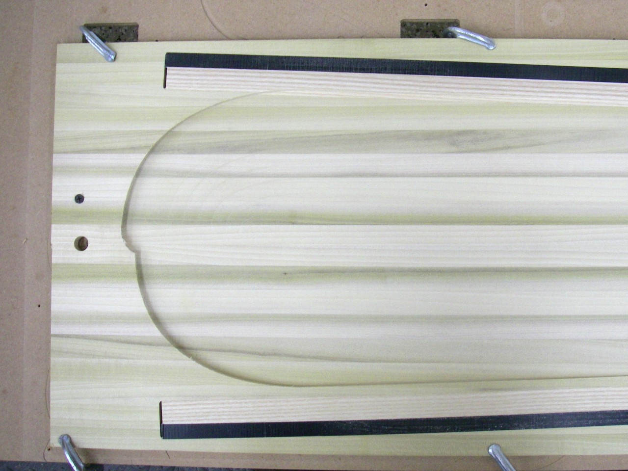
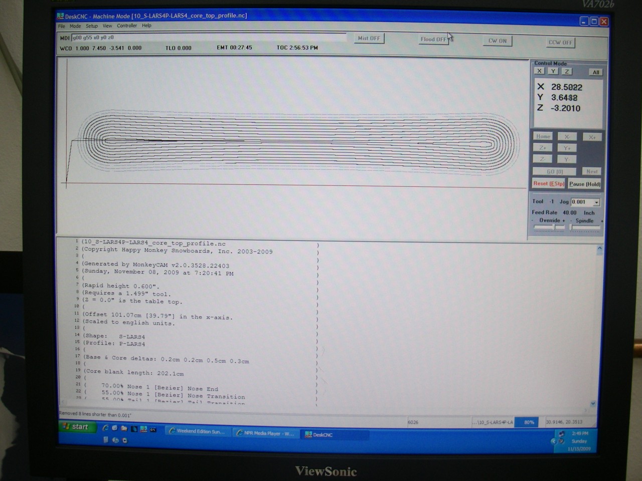
Thickness profile #
The thickness profile is applied to the core with a 1.5” cutter in multiple concentric passes. I start from the center and work outwards until the entire surface of the final core is profiled. My CNC machine was designed to provide very precise control over the depth of the cutter, and our custom software (MonkeyCAM) generates smooth splines for the ramps from nose to center to tail.
Because the stiffness of the board is largely determined by the thickness of the core, I want the tolerance of this process to be +/- 0.0025”. The Z axis of my CNC machine is over-engineered to ensure that it can adjust the depth of the cutter much less than 0.001”, and in a perfect world that would be enough. However, expansion of the wood due to heat from the cutter, imperfections in holding the core blank to the table, etc. end up ensuring that this step can never be perfect. My experience has been that with careful work holding, the thickness comes out within tolerance that vast majority of the time.
Thickness profile #
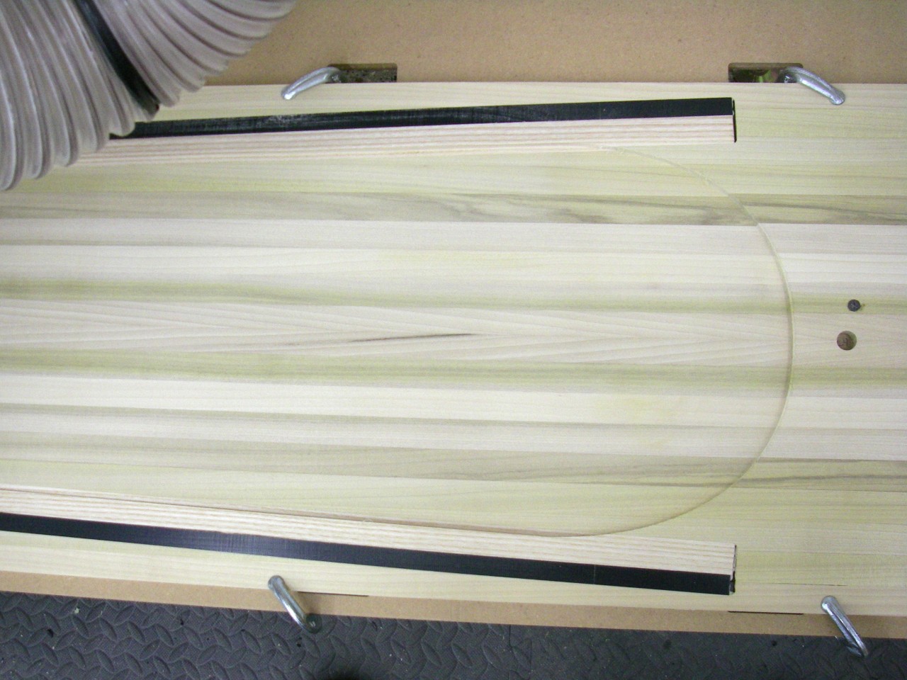
Cut out and final cleanup #
The last step on the CNC machine is to apply the final overall shape to the core, and cut it out. This is done in multiple shallow passes, as the core gets more and more delicate as it progresses through all of these machining steps. At this point, the nose and tail are typically 0.080” thick, and the sidewall material is just as thin near the ends of the effective edge. Holding the work properly at this stage is critical to a successful cutout. Four small tabs are left to hold the core to the remaining part of the blank. This keeps the core stable for the final pass. These are carefully cut through by hand at the workbench, releasing the final core from the rest of the blank.
Finally, a little time is spent at the work bench with the edges of the core. I carefully remove any fuzz left by the router bits with a bit of sandpaper or a block plane.